Constant Thickness dimensions
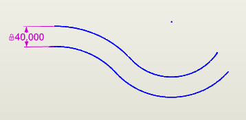
Constant Thickness dimensions let you define stock material thickness by automatically copying and offsetting selected geometry and applying a single dimension for the thickness between the resulting set of geometry.
The Constant Thickness feature is useful for modeling stamped sheet-metal parts for which the thickness of the material is assumed to be consistent throughout the part (i.e., "global" variation). If modeling extruded or injection-molded components, where the thickness of different features can vary independently of each other, use the Profile Emulation tolerance setting as described below to simulate a profile tolerance.
To place a Constant Thickness dimension:
- Select the Constant Thickness Dimension tool
 from the Sketch toolbar.
 - Select the geometry that will act as the base side of the constant thickness part and then press Enter to accept the selection, or select a polycurve.
-
Move the mouse cursor to position the ghost image of the offset geometry and click to place in the desired position.
Working with Constant Thickness dimensions
Note the following when working with Constant Thickness dimensions:
- The outer radius of any bend in the geometry must be greater than the thickness of the material.
- The geometry selected for the Constant Thickness dimension cannot have sharp corners and must be constrained tangent.
- You can perturb the entire length of the constant thickness part, or you can perturb one element (individual segments of geometry and dimensions that compose the part) at a time.
-
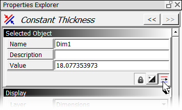
Selecting the element to perturb has no effect on the dimension display. For example, if you select the dimension associated with the first of three elements that compose the length of a constant thickness part, and then select "Element 2" to perturb, the first dimension remains highlighted in the sketch. To move from one element's dimension to the next in the sketch, use the switch position button in the Selected Objects area of the Properties Explorer:
-
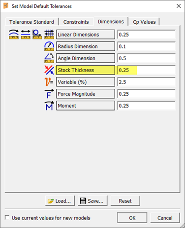
You can set the default tolerance for a Constant Thickness dimension using the Stock Thickness setting in the Set Model Default Tolerances dialog (accessed using Default Tolerances from the Edit menu). The default Stock Thickness setting is 0.
Simulating a profile tolerance using a Constant Thickness constraint
The Constant Thickness tool was originally intended for stamped-metal applications. Therefore, this tool normally applies "global" variation (i.e., if the sheet metal is thicker or thinner than the nominal size, that variation exists throughout the entire part) with only small amounts of localized variation.
To support simulating profile tolerances, Enventive Concept includes a Profile Emulation tolerance type. Rather than using global variation, setting the tolerance type to Profile Emulation allows each element to be mathematically independent, as if there were separate dimensions controlling the variation of each point.
You may also use a Point on Object constraint to simulate a profile tolerance, which is somewhat easier. but (drawbacks and ref.)
To simulate a profile tolerance using a Constant Thickness constraint:
- Draw the desired geometry and constrain it using basic dimensions to describe where the theoretically perfect surface should be.
- Assign this geometry to a separate layer, so that it can be hidden easily.
- Use the Constant Thickness tool to create a set of offset geometry, as described above.
- Select the Constant Thickness dimension so that you can see its settings in the Properties Explorer. (You may need to select the offset geometry, and then select the Constant Thickness dimension from the list of Connected Objects.)
-
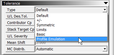
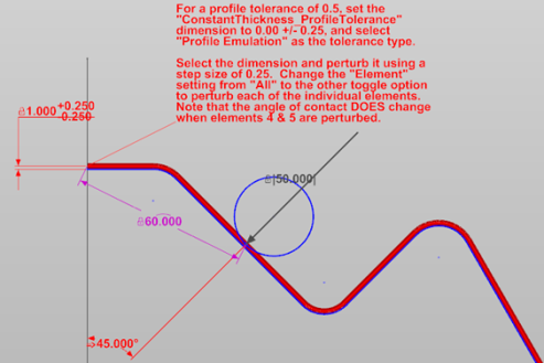
Select the Profile Emulation option as the tolerance type for the Constant Thickness constraint.
- Assign a ± tolerance range equal to the total Profile tolerance. (For example, for a Profile tolerance of 0.5, set the tolerance to ±0.25.)
-
Set the nominal value for the offset dimension to zero, and hide the original geometry.
Note: The disadvantage of this method is that it generally takes a bit longer to set up than the Point on Object method, and the Constant Thickness tool does not support sharp corners—lines and arcs must be tangent.